Basic Electrocardiography
In our first three lessons we discussed various aspects of normal cardiac anatomy and physiology. Here we will bring it all together to see how physicians use the electrocardiogram to detect and evaluate heart disease. It is important to have a basic background in the detection and significance of arrhythmias to assist with exercise treadmill testing. Being able to differentiate normal and abnormal electrocardiograms is crucial for identifying some of the abnormalities that may appear during myocardial perfusion imaging.
The electrocardiogram (“ECG”, “EKG”) records the electrical activity of a large mass of atrial and ventricular cells as specific waveforms and complexes. The electrocardiographic monitor is a voltmeter that records the electrical potentials generated by the cyclic depolarization and repolarization of heart muscle. This electrical activity is visually recorded by means of electrodes connected by cables to an electrocardiograph machine.
ECG recording paper is ruled in 1 mm lines horizontally and vertically. When the tracing is properly standardized*, each vertical space represents a voltage change of 0.1 millivolt. Each horizontal space represents a time interval of 0.04 second when the chart paper is moving at 25 mm per second. Each fifth horizontal and vertical line is heavy. The time interval between two of the heavy vertical lines is 0.2 second. The voltage between two of the heavy horizontal lines is 0.5 millivolt.
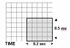
Each 5 mm x 5 mm block of squares is separated by a grid of bold lines. The height and depth of each wave of polarization and depolarization are measured in millimeters, and are recorded on the EKG as shown.
Electrodes and Electrocardiographic Leads
Electrical currents can be detected at the surface of the body with electrodes placed on the skin, applied at specific locations on the patient’s chest wall and extremities to view the heart’s electrical activity from different angles and planes. One end of a monitoring cable is attached to the electrode and the other to an ECG machine. The routine ECG records twelve leads using 10 electrodes. For exercise stress electrocardiography, the standard 12-lead positioning must be slightly modified to permit increased mobility. The limb leads are positioned over the left and right superior clavicular region for the arm leads, and over the left and right lower quadrants of the abdomen for the leg leads. This placement permits reduces motion artifacts during exercise.
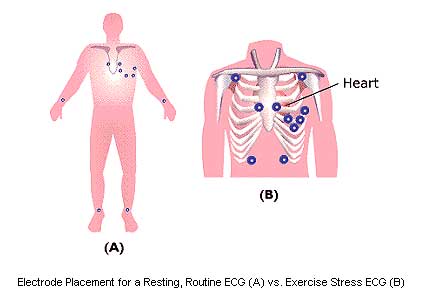
DETAILED VIEW OF ELECTRODE PLACEMENT FOR EXERCISE STRESS TESTING

V1 and V2 are placed over the right side of the heart. Leads V3 and V4 are placed over the interventricular septum, a common wall shared by the Right and Left ventricle. In this area the AV Bundle divides into the Right and Left Bundle Branches. V5 and V6 are placed over the left side of the heart.
The electrocardiographic lead, the basic component of monitoring and recording devices, is a record of electrical activity between two electrodes. Each lead records the average current or flow at a specific time in a portion of the heart. A galvanometer is connected to a negative electrode and a positive one, and measures the current flowing between them. To obtain a recording of electrical activity, a writing stylus is attached to the galvanometer in such a way that it moves with the current indicator. Limb leads, augmented limb leads, and precordial (chest) leads are the conventional electrical connections used for recording the electrocardiogram. The limb leads provide six differing views of the heart in the frontal plane using four electrodes placed on the arms and legs. The six precordial or chest leads provide six different views of the heart in the horizontal plane using six electrodes placed at precise locations on the chest.
- Limb leads: I, II, III (“bipolar leads”)
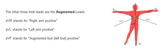
- Augmented leads: aVR, aVL, aVF (“unipolar leads”)
- Precordial leads: V1, V2, V3, V4, V5, V6 (“unipolar leads”)
Each lead records the heart’s electrical impulses on the ECG from a different position in relation to the heart. Leads allow viewing of the heart’s electrical activity in two different planes: frontal (coronal) or horizontal (transverse). Frontal plane leads view the heart from the front of the body. Directions in the frontal plane are superior, inferior, right, and left. Horizontal plane leads view the heart as if the body were sliced in half horizontally. Directions in the horizontal plane are anterior, posterior, right, and left.
A 12-lead ECG views the surfaces of the left ventricle from 12 different angles. The limb leads show the current flow from one area of the body toward another. Lead I records electrical activity from the right arm to the left arm, lead II from right arm to left leg, and lead III from left arm to left leg. The augmented limb leads (aVR, aVL, aVF) measure the electrical potential between the right arm, left arm, and left leg, respectively, and the center of the heart. These augmented leads tend to increase the wave-deflection amplitude of the limb leads by approximately 50%.
The leads relate to the anatomy of the heart in the following way:
V1, aVR- right side of heart
V2, V3, V4- transition between right and left sides of heart
V5, V6, I, aVL- left side of heart
II, III, aVF- inferior part of the heart
By knowing what part of the heart each lead represents, the clinician can localize the area of pathology shown on the ECG. For example, if an infarct is detected on leads II, III, and aVF only, it is presumed to be in the inferior part of the heart.
The three limb leads, three augmented limb leads, and six precordial leads comprise the standard 12-lead electrocardiogram generally used in cardiology.
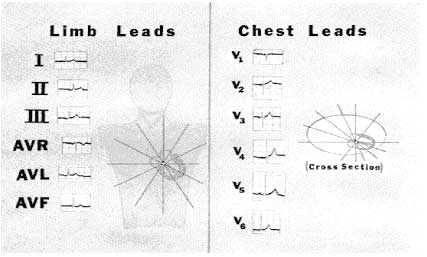
Limb Leads
The standard EKG is composed of 12 separate leads: six limb leads and six chest leads. Limb leads include: I, II, III, aVR, aVL, aVF

To obtain the limb leads, electrodes are placed on the right and left arms and the left leg forming “Einthoven’s triangle”, where each side of the triangle formed by the three electrodes represents a lead using different electrode pairs for each lead.
By pushing these three leads to the center of the triangle, our three lines of reference intersect to lie in the frontal plane.
The aVR lead uses the right arm as positive and all other limb electrodes as a (common) ground (negative). (The right foot sensor is never connected while monitoring the augmented leads.)
The aVL lead uses the left arm as positive, while the other limb sensors in aVL are then channeled into a ground and are considered negative. The positive sensor in aVF is on the left foot.
The aVR, aVL and aVF leads intersect at different angles and produce three other intersecting lines of reference intersecting at 60 degree angles.
Observation from six angles is better than one: thus monitoring cardiac electrical activity from six different angles gives us a much greater perspective.
Chest Leads
To obtain the six chest leads, a positive electrode is placed at six different positions around the chest. The chest leads numbered from V1 through V6 move in successive steps from the patient’s right to his left side.
The chest leads cover the heart in its anatomical position within the chest. The chest leads are projected through the AV node towards the patient’s back, which is the negative end of each chest lead. The chest leads progressively encircle the heart in the horizontal plane, intersecting at the AV node, which cuts the body into top and bottom halves.
An EKG tracing will show progressive changes from V1 to V6. The QRS complex is mainly negative in lead V1 and mainly positive in lead V6. The positive wave of ventricular depolarization is moving toward the positive chest electrode of V6.
On a standard EKG mounting, the six chest leads and six limb leads are placed in a column. This is a 12 lead electrocardiogram.
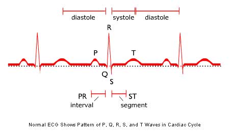
The Normal Electrocardiogram
The normal ECG is characterized by the wave form shown below. Each of the individual segments of the wave is designated by a letter (or letters), and each represents a distinct phase of the cardiac cycle.
The electrodes placed on the skin are positive terminals attached to lead wires. When a wave of depolarization advances toward a positive electrode, this produces a positive (upward) deflection on EKG. The advancing wave of positive charge in depolarization creates a positive deflection on EKG when this wave is moving toward a positive skin sensor.
*A 1- millivolt change produces a 10 mm stylus deflection.